


1
Alternate Path
Do not discard the hardware bags or mix parts from different bags. Make note of the symbol printed on each hardware bag. The symbols can be used to identify the appropriate hardware for each step.
Pro Tip
Do not discard the hardware bags or mix parts from different bags. Make note of the symbol printed on each hardware bag. The symbols can be used to identify the appropriate hardware for each step.
|
|
bags here
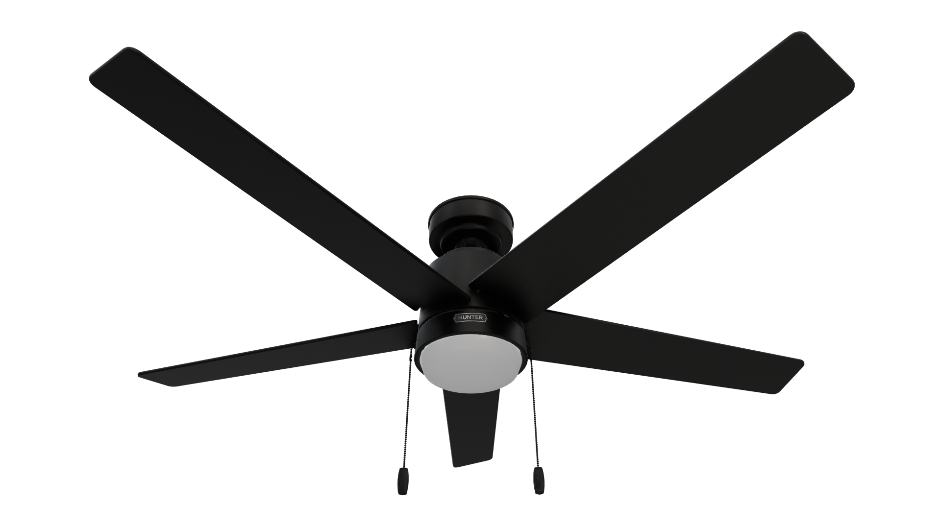
CEILING BRACKET: STEP 1
This is dummy copy not actual copy. Before diving into installation, switch off the power. This is dummy copy not actual copy. Before diving.
0
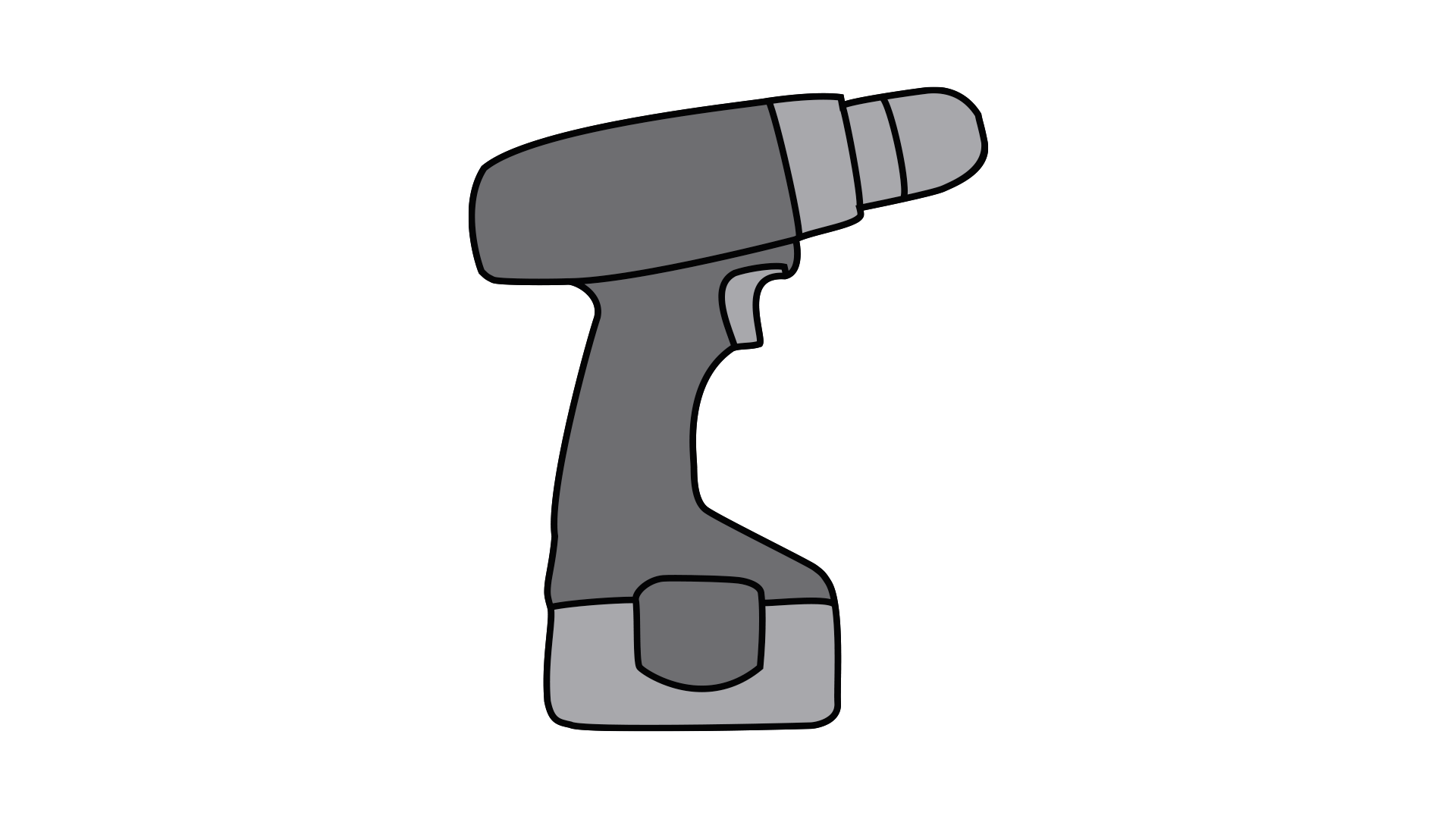
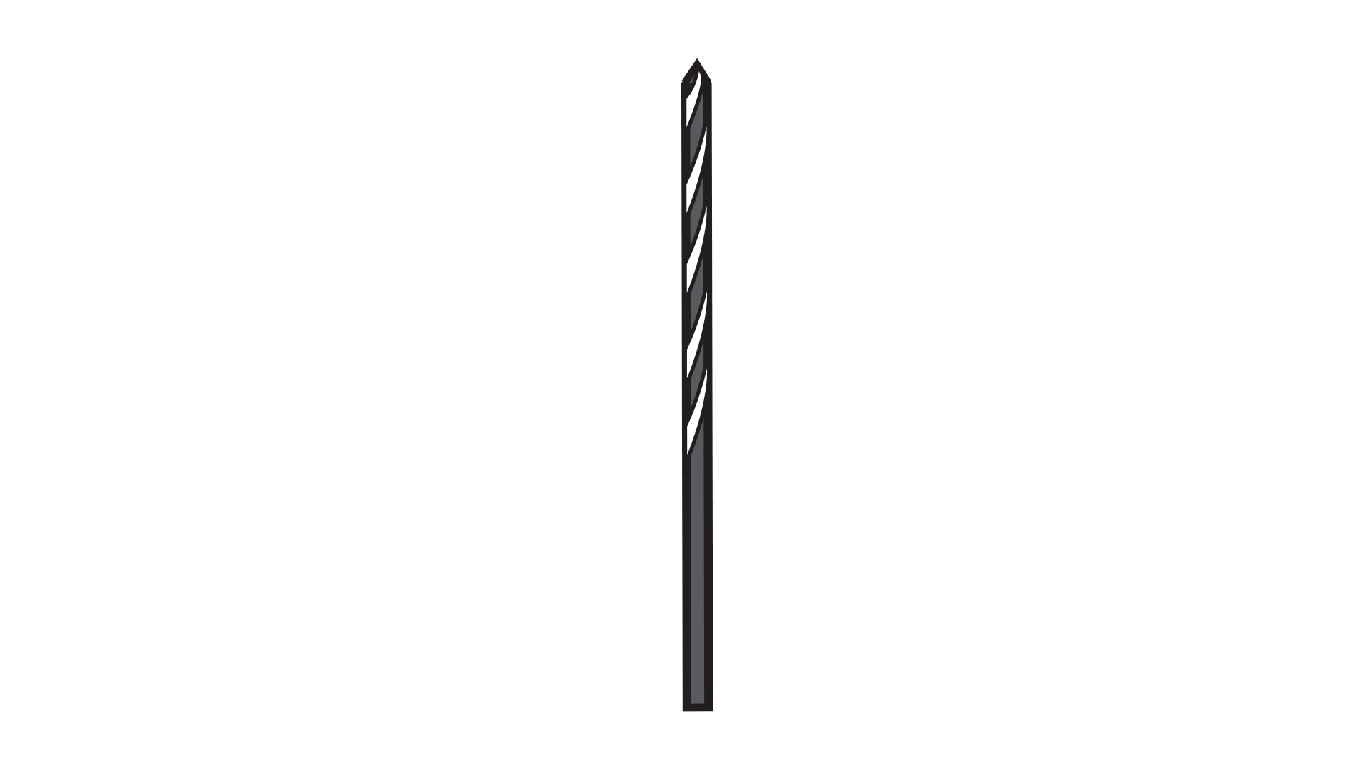
Tools & Parts
Needed for current Step
Accesories
Get the most out of your product with these recommended Accesories
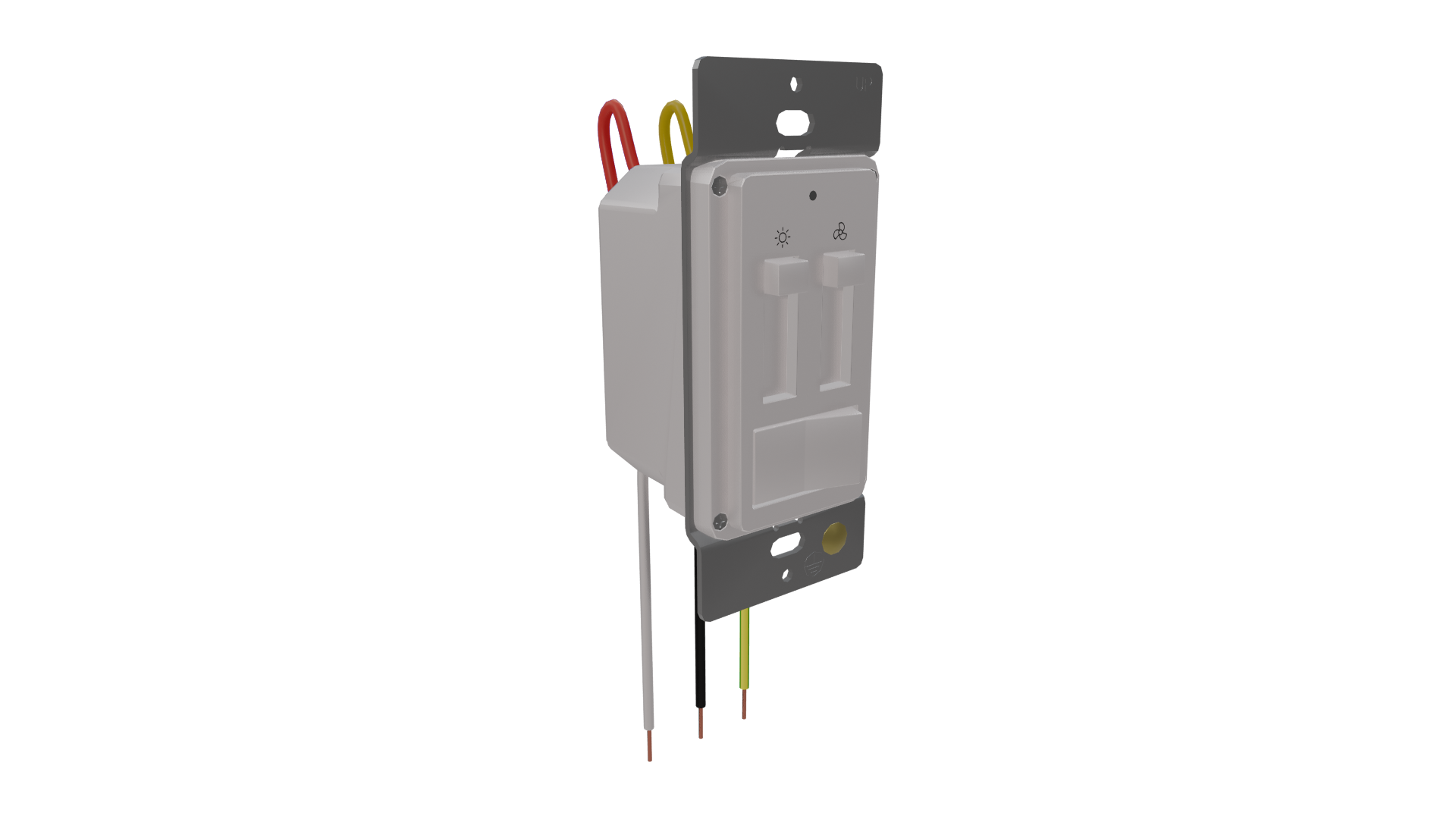
Installation
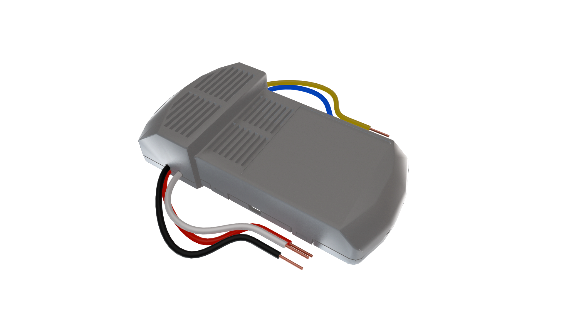
The Hunter Multi-Fan Wall Control requires an installed compatible receiver to function. Please follow the installation instructions included with the receiver prior to setting up your Multi-Fan Wall Control.
Can connect additional fans (up to 10 in total) by wiring each fan’s receiver in succession from the initial fan. For proper operation, ensure all connected ceiling fans are on the same electrical circuit. The wall control can only communicate with fans that are ‘downstream’ on the same circuit.
1. The total load of all fans should not exceed 12 amps. Not for use with any other lighting fixtures or electrical appliances.
2. - Not for use with shaded-pole motors. Not recommended for use with the Hunter Original®. For Hunter Original® series fans, use Hunter control model numbers 22691, 27189, or 27187.
3. - This control requires separate wiring for the ceiling fan and fan light kit. If one wall switch currently supplies power to both the fan and light, additional wiring for the light fixture will be required to use this Hunter control.
4. For optimal use only control multiple fans of the same type.
5. All fans must have the compatible gray receiver with red wire to function, excluding Hunter Integrated Receiver AC/DC fans.
Ceiling Fan Compatability
Use the below compatability details to determine if a receiver is needed to connect your fan(s) to your Multi-Fan wall control(s)*Accessory Receiver Required
• AC Motor Pull Chain: Multi-Fan Receiver - AC Fans 99817
• AC Motor Canopy Receiver:Multi-Fan Receiver - AC Fans 99817
• Hunter DC Motor Canopy Receiver Remote Control:Additional receiver not required if receiver is gray with red wire.
• Hunter Integrated Receiver :Additional receiver not required
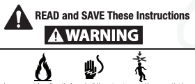
Warning
w.1 - To reduce the risk of fire, electrical shock, or personal injury, mount fan directly from building structure and/or an outlet box marked acceptable for fan support of 70 lbs (31.8 kg) and use the mounting screws provided with the outlet box.
w.2 - To avoid possible electrical shock, before installing or servicing your fan, disconnect the power by turning off the circuit breakers to the outlet box and associated wall switch location. If you cannot lock the circuit breakers in the off position, securely fasten a prominent warning device, such as a tag, to the service panel.
w.3 – To reduce the risk of electric shock, this fan must be installed with an isolating wall control/switch.
w.4 - To reduce the risk of personal injury, do not bend the blade brackets when installing the blade brackets, balancing the blades, or cleaning the fan. Do not insert foreign objects in between rotating fan blades.
w.5 - This appliance can be used by children aged from 8 years and above and persons with reduced physical, sensory or mental capabilities or lack of experience and knowledge if they have been given supervision or instruction concerning use of the appliance in a safe way and understand the hazards involved. Children shall not play with the appliance. Cleaning and user maintenance shall not be made by children without supervision. It is recommended that children be supervised to ensure that they are not using the appliance improperly.
w.6 - To reduce the risk of fire or electric shock or injury to persons, do not use replacement parts that have not been recommended by the manufacturer (e.g. parts made at home using a 3D printer).
Caution
c.1 - All wiring must be in accordance with national and local electrical codes ANSI/NFPA 70. If you are unfamiliar with wiring, use a qualified electrician.
c.2 - Use only Hunter replacement parts.
• Reorient or relocate the receiving antenna.
• Increase the separation between the equipment and receiver.
• Connect the equipment into an outlet on a circuit different from that to which the receiver is connected.
• Consult the dealer or an experienced radio/TV technician for help.
Caution: modifications not approved by the party responsible for compliance could void user’s authority to operate the equipment.
This device complies with Part 15 of the FCC Rules. Operation is subject to the following two conditions: (1) This device may not cause harmful interference, and (2) this device must accept any interference received, including interference that may cause undesired operation.
This device complies with RSS-210 of Industry Canada. Operation is subject to the following two conditions: (1) this device may not cause interference, and (2) this device must accept any interference, including interference that maycause undesired operation of the device.
Start now for Seamless Setup
| Tools |
1 More |
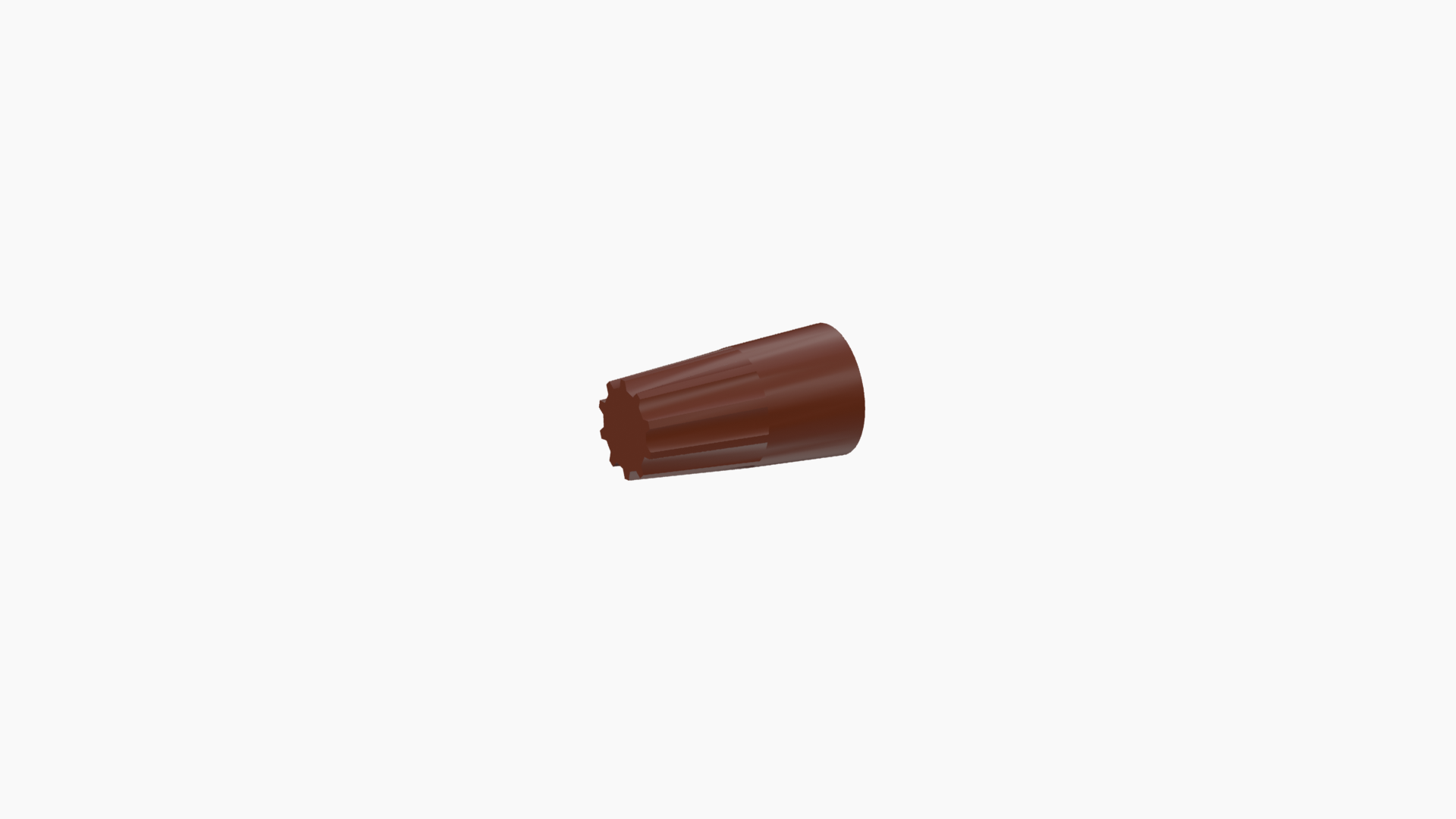
| Parts |
2 More |
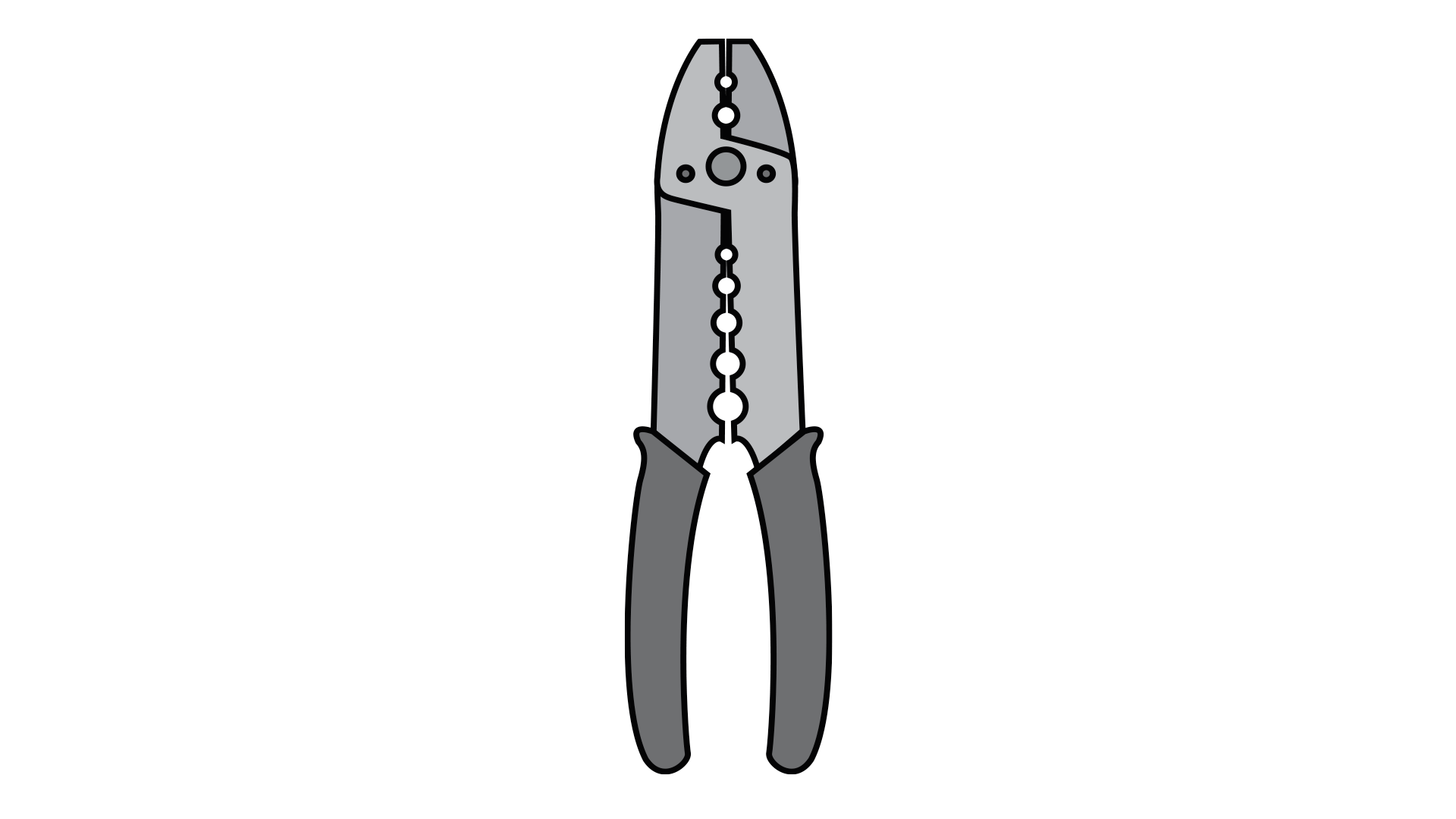
Tools Needed
Ladder
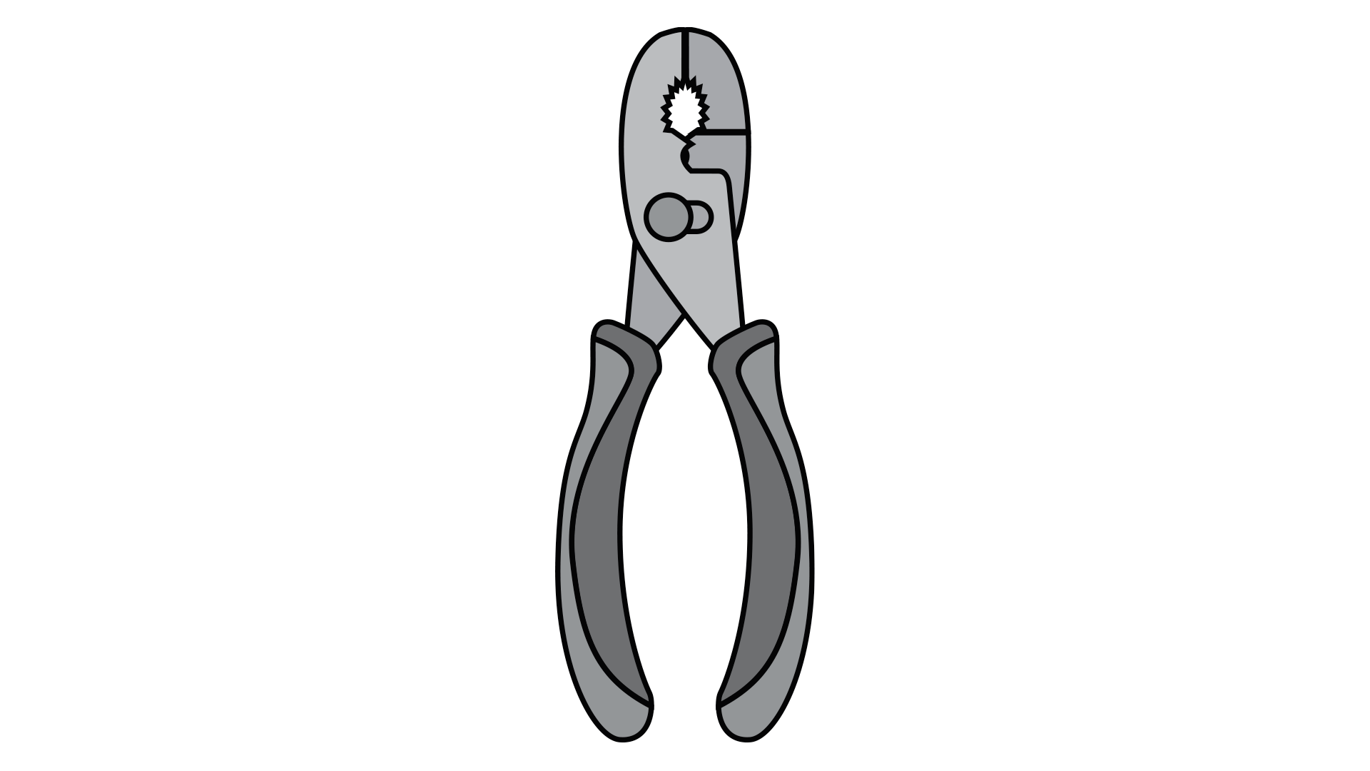
Pliers

Wirestripper
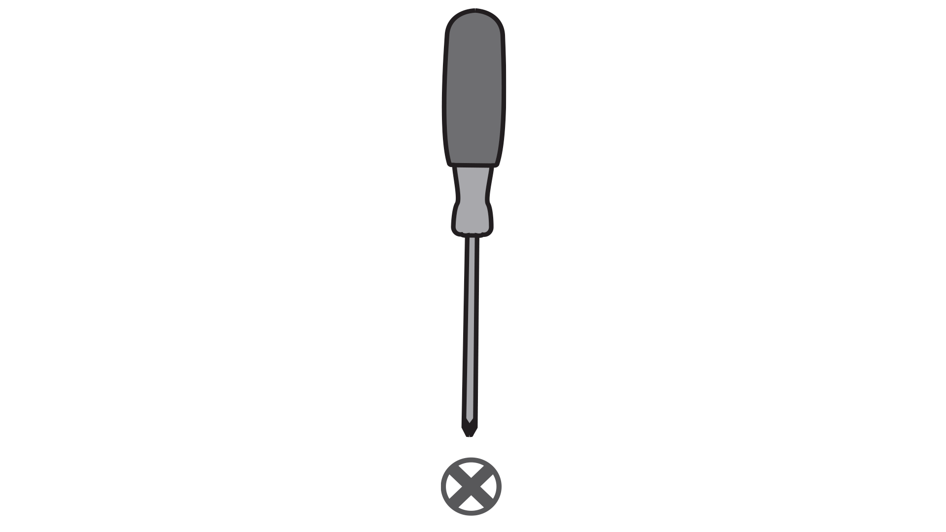
Phillips-Head Screwdriver
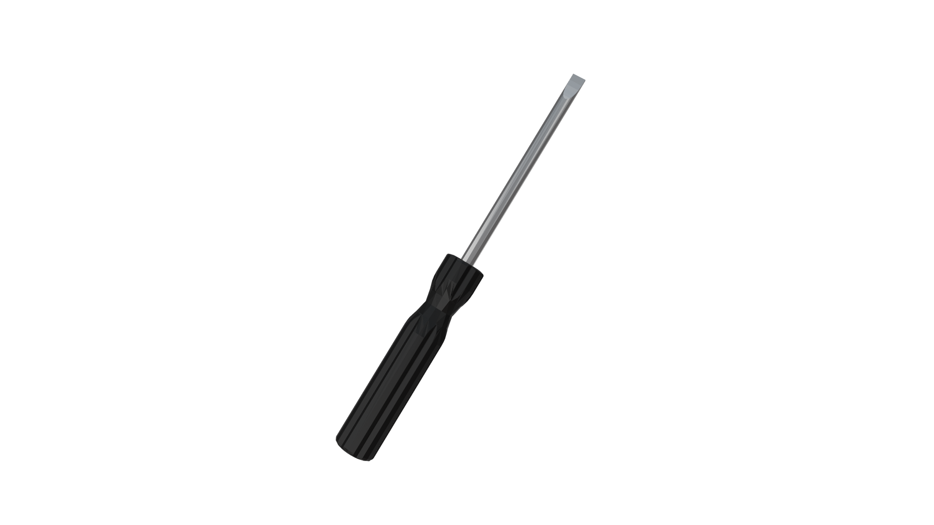
Flat-Head Screwdriver
Please rate the installation experience:


Thank you for your feedback.
How can we improve next time?
|
|
|
CEILING BRACKET: STEP 1This is dummy copy not actual copy. Before diving into installation, switch off the power. This is dummy copy not actual copy. Before diving. |
|
|
Step
|
|
0
|
|
0